|
Copyright © NOVEMBER, 2006 - NOVEMBER, 2014
Arthur John Huneke
ALL RIGHTS RESERVED
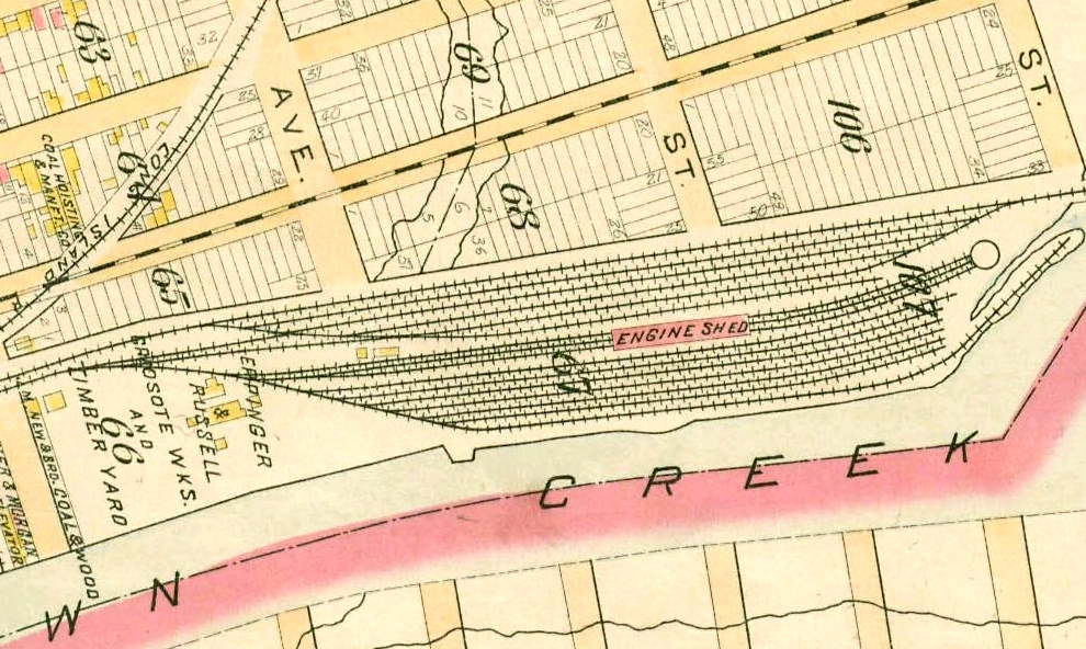
FROM AN 1891 ATLAS
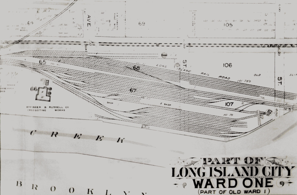
FROM A 1903 ATLAS
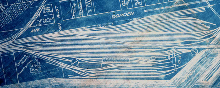
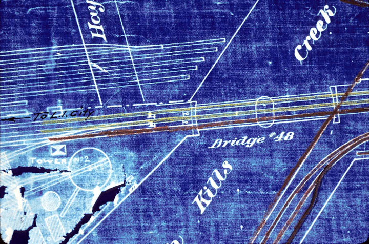
THIS BLUEPRINT IS CIRCA 1910.
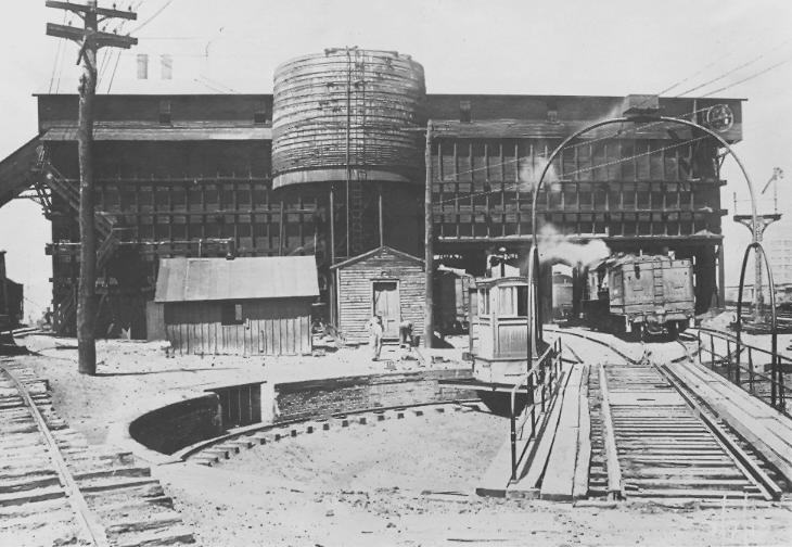
TWO TURNTABLES - ONE SIXTY FEET, THE OTHER SEVENTY FEET
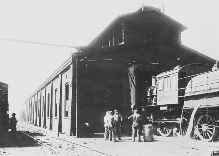
TWO ENGINE HOUSES - TWO COALING TOWERS -
ONE ABLE TO FUEL FIVE LOCOMOTIVES AT THE SAME TIME
TAKE NOTE OF THE PENNSYLVANIA TUNNEL and TERMINAL RAIL ROAD
COMPANY (P.T.& T.R.R.) WATER TANK AT THE UPPER LEFT OF THIS PLAN
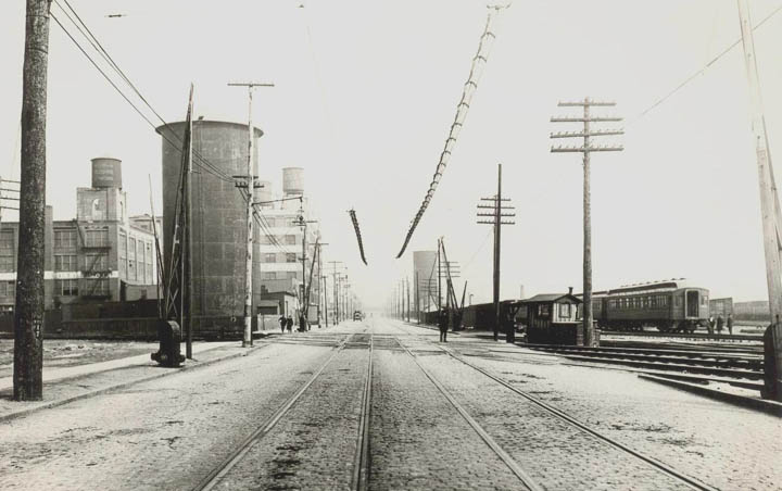
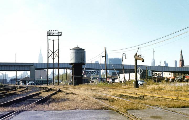
LOOKING EAST ON BORDEN AVENUE IN 1915
THE P.T.& T.R.R. 250,000 GALLON WATER TANK IS NORTH AND EAST OF THE CROSSING
BILL WEST ENLIGHTENS US WITH THIS INFORMATION:
THANKS BILL!
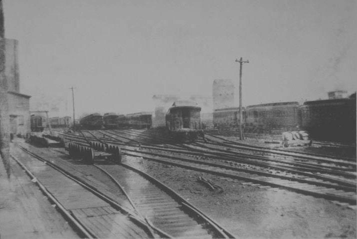
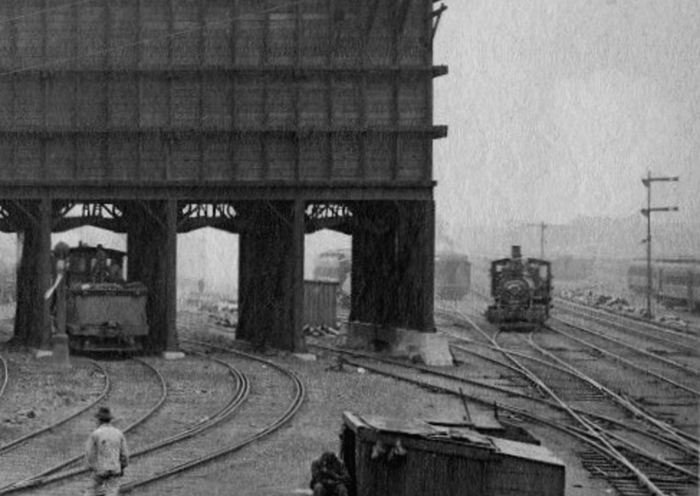
LOOKING TOWARD YARD FROM THE NORTHWEST CIRCA 1918
IN NOVEMBER 1955 THERE WERE STILL A WATER TOWER AND PLUG
ENGINE FACILITIES
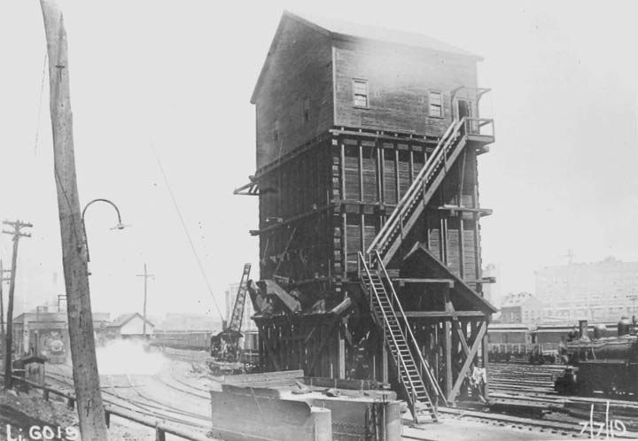
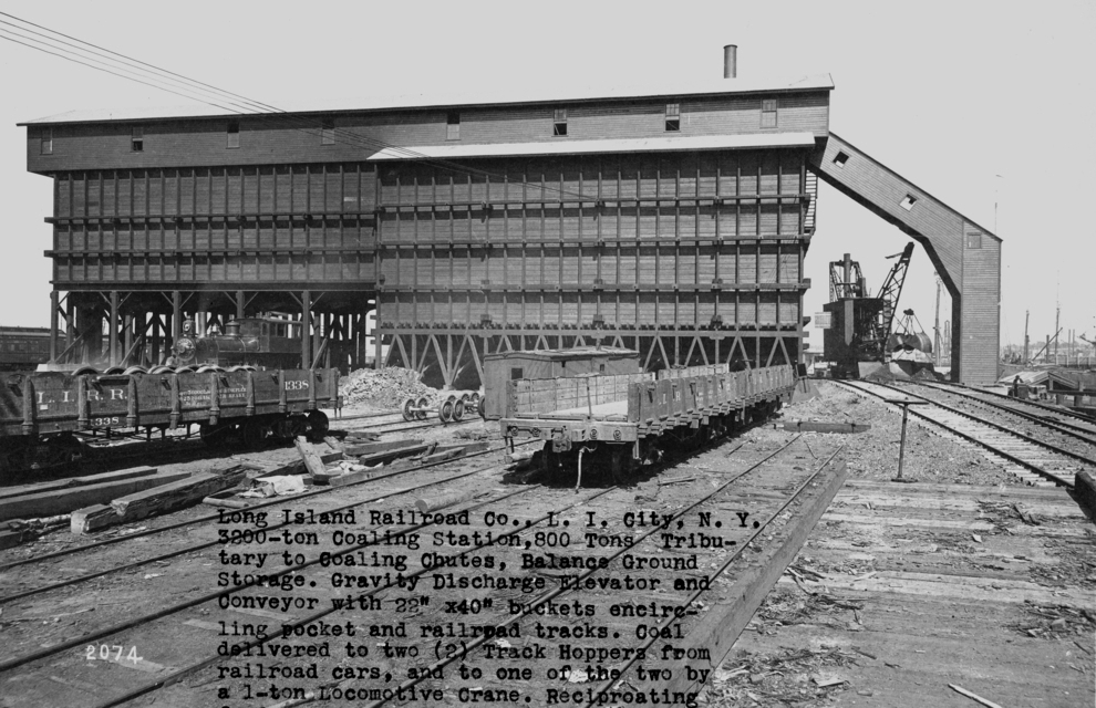
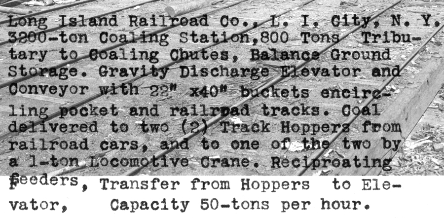
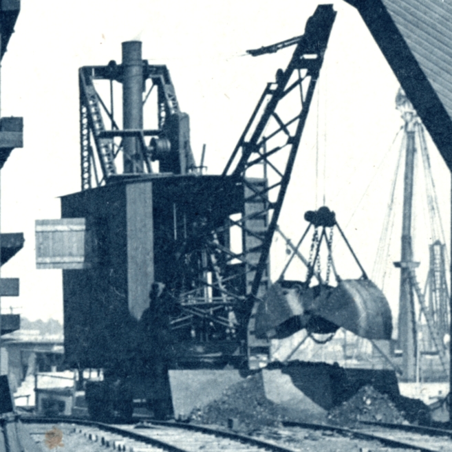
ANNUAL REPORT OF JUNE 1898 REPORTED COMPLETION OF "COAL POCKETS AT LONG ISLAND CITY"
THAT MAY HAVE REFERRED TO THIS COAL TOWER.
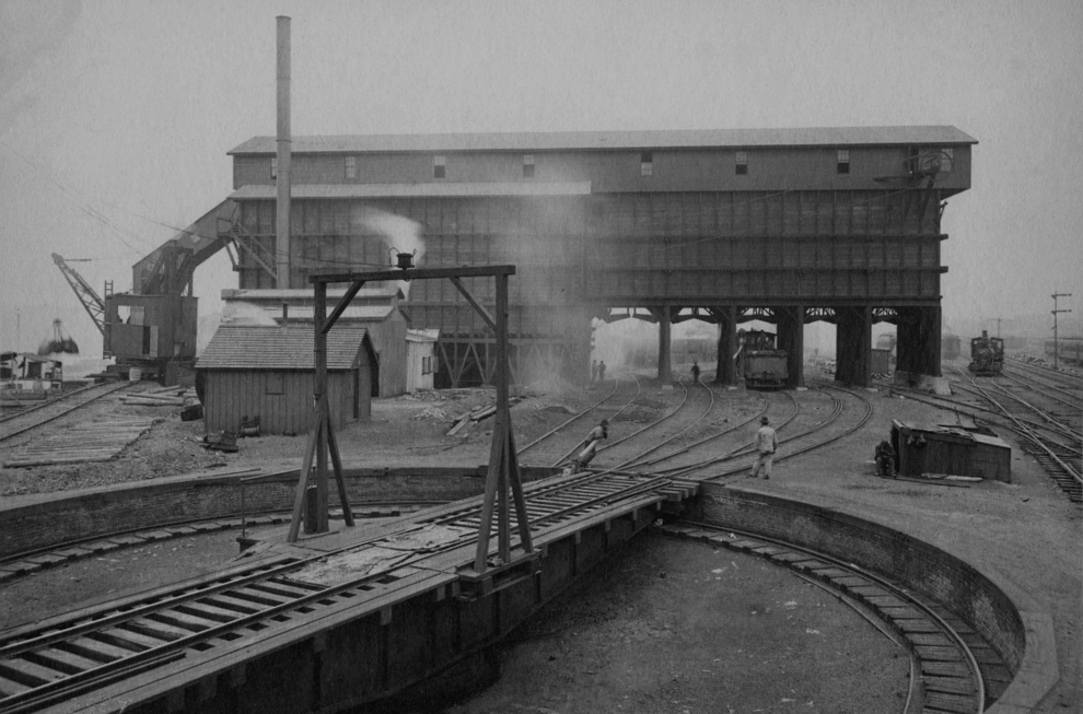
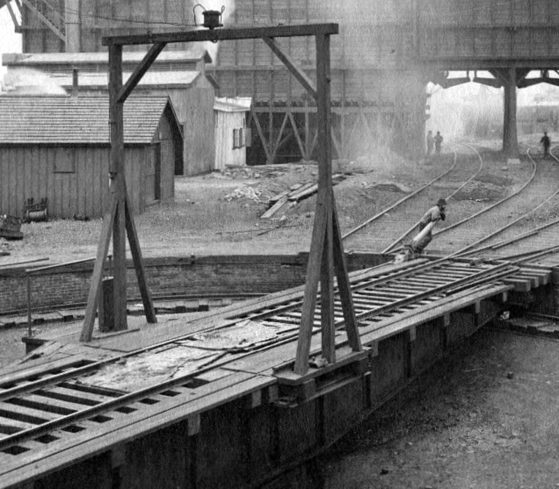
THE TURNTABLE WAS ELECTRIC. WE BELIEVE THIS WAS CONSIDERED A MODIFIED A-FRAME GALLOWS STYLE
TABLE. THE CONTROL STAND APPEARS TO BE ADJACENT TO THE GALLOWS UPRIGHT BEAM AND UNPROTECTED.
ONLY FOUR TRACKS LEAD TO THE FIVE COAL TIPPLES.
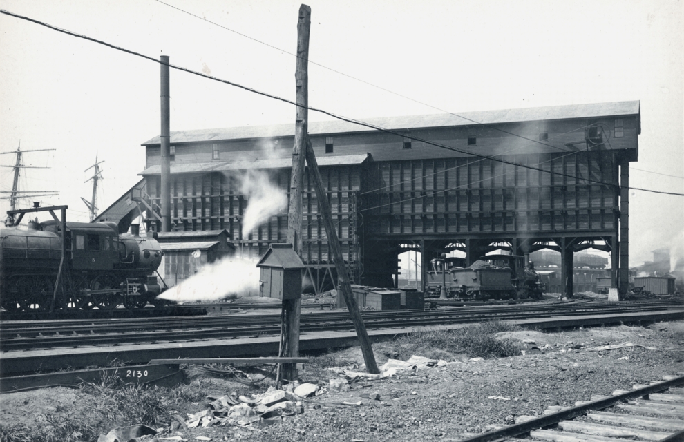
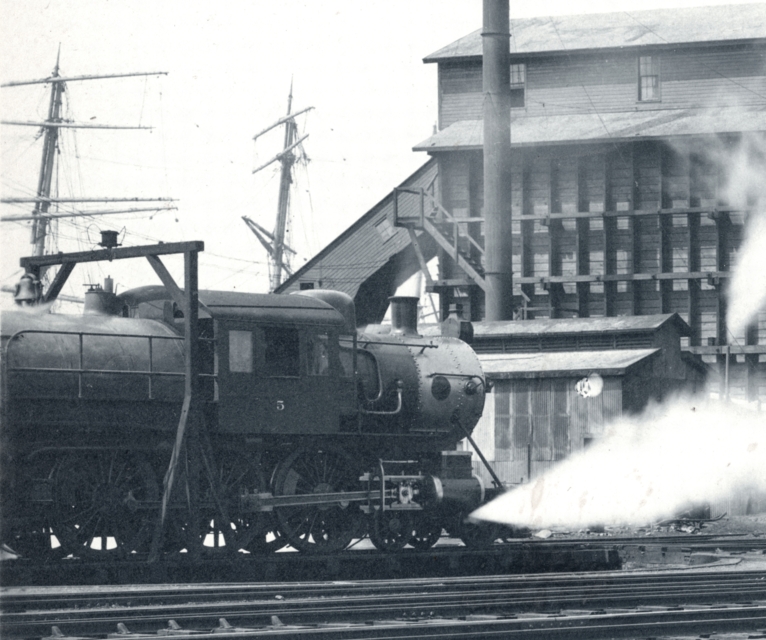
G54a NUMBER FIVE WAS BUILT IN 1901
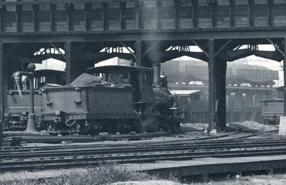
BY 1919 A WATER TOWER HAD BEEN ADDED AND THE TURNTABLE HAD A METAL YOKE (?) TYPE
GALLOWS AND A CONTROL CABIN. PERHAPS THIS TURNTABLE HAD REPLACED THE PREVIOUS ONE.
TOWER NUMBER TWO - "DB"
IN 1891 THERE WERE NO TOWER AND NO YARD NORTH OF THE MAIN TRACKS
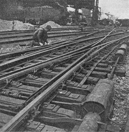
CHECK OUT THE DOUBLE GUARD RAILS!
THE SIGNAL AT THE CENTER WAS CONTROLLED FROM TOWER NUMBER TWO'S MECHANICAL MACHINE.
THE PIPELINE WAS COVERED BY THE WOODEN TRUNKING IN THE FOREGROUND.
THIS IS 1903 - 04
THESE TWO PHOTOGRAPHS ACCOMPANIED THE ARTICLE.
Arthur John Huneke
ALL RIGHTS RESERVED
| | STORAGE YARD - ENGINE FACILITIES
|
FROM AN 1891 ATLAS
FROM A 1903 ATLAS
|
Annual Report for June 1903 - June 1904 shows under "...charges to Extraordinary Expenditure Fund....." Storage Tracks L.I.City..... Turntable on dock at L.I.City..... Increased facilities.....in the passenger yard at that point ..... |
THIS BLUEPRINT IS CIRCA 1910.
TWO TURNTABLES - ONE SIXTY FEET, THE OTHER SEVENTY FEET
TWO ENGINE HOUSES - TWO COALING TOWERS -
ONE ABLE TO FUEL FIVE LOCOMOTIVES AT THE SAME TIME
TAKE NOTE OF THE PENNSYLVANIA TUNNEL and TERMINAL RAIL ROAD
COMPANY (P.T.& T.R.R.) WATER TANK AT THE UPPER LEFT OF THIS PLAN
LOOKING EAST ON BORDEN AVENUE IN 1915
THE P.T.& T.R.R. 250,000 GALLON WATER TANK IS NORTH AND EAST OF THE CROSSING
BILL WEST ENLIGHTENS US WITH THIS INFORMATION:
|
In your recent “Long Island City Part Three” pages, the first map and first picture show a large steel PT&T RR water tank on a triangle of land at Borden and Van Alst. When Sunnyside was being built the consultants drilled test wells around the yard to find a good supply of water. They chose two near Harold Ave and connected them to pumps in the yard powerhouse. They were then piped to this 250,000 gallon storage tank to supply Sunnyside yard and LI City Generating station. The generator turbines had previously been using an expensive type of condenser to avoid buying expensive city water for boiler feed. This is from ASCE Transactions paper #1163 and also #1165 by Gibbs 1910.
|
THANKS BILL!
LOOKING TOWARD YARD FROM THE NORTHWEST CIRCA 1918
IN NOVEMBER 1955 THERE WERE STILL A WATER TOWER AND PLUG
ENGINE FACILITIES
ANNUAL REPORT OF JUNE 1898 REPORTED COMPLETION OF "COAL POCKETS AT LONG ISLAND CITY"
THAT MAY HAVE REFERRED TO THIS COAL TOWER.
THE TURNTABLE WAS ELECTRIC. WE BELIEVE THIS WAS CONSIDERED A MODIFIED A-FRAME GALLOWS STYLE
TABLE. THE CONTROL STAND APPEARS TO BE ADJACENT TO THE GALLOWS UPRIGHT BEAM AND UNPROTECTED.
ONLY FOUR TRACKS LEAD TO THE FIVE COAL TIPPLES.
G54a NUMBER FIVE WAS BUILT IN 1901
BY 1919 A WATER TOWER HAD BEEN ADDED AND THE TURNTABLE HAD A METAL YOKE (?) TYPE
GALLOWS AND A CONTROL CABIN. PERHAPS THIS TURNTABLE HAD REPLACED THE PREVIOUS ONE.
TOWER NUMBER TWO - "DB"
IN 1891 THERE WERE NO TOWER AND NO YARD NORTH OF THE MAIN TRACKS
|
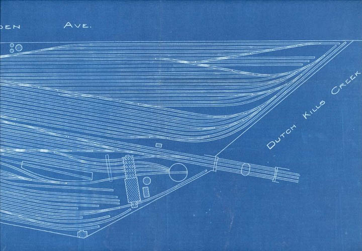
Blueprint shows area between 1892 when the Block System was installed and 1903 - 1904. Tower Number 2 was a block station and interlocking and controlled signals protecting the drawbridge and switches and signals at the entrance to the south yard. Note that the switch from tracks on drawbridge is further east than in the later blueprint and in foto and the track leads to the north coal tipple. |
|
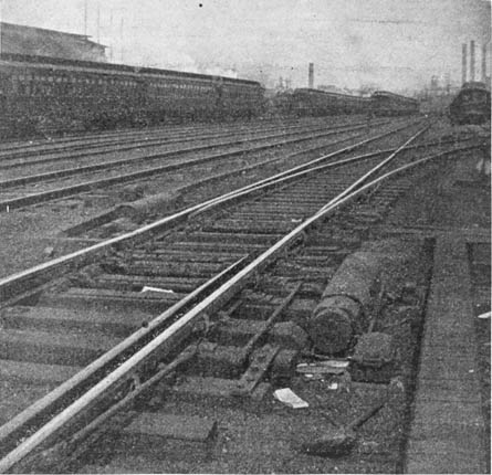
When the yards were enlarged in 1903-04 the tower was moved or a new tower with a mechanical machine was built north of the main tracks. The switches at the right and the signals at the center and right were controlled from Tower number Two's mechanical machine.
|
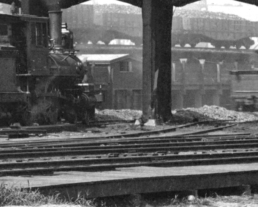
CHECK OUT THE DOUBLE GUARD RAILS!
THE SIGNAL AT THE CENTER WAS CONTROLLED FROM TOWER NUMBER TWO'S MECHANICAL MACHINE.
THE PIPELINE WAS COVERED BY THE WOODEN TRUNKING IN THE FOREGROUND.
THIS IS 1903 - 04
|
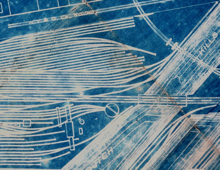
After the north yard was enlarged its east end was connected by double slip switches with the Dock Yard as seen in 1908 foto and this blueprint. Notice that the entrance to engine yard is now further west. |
|
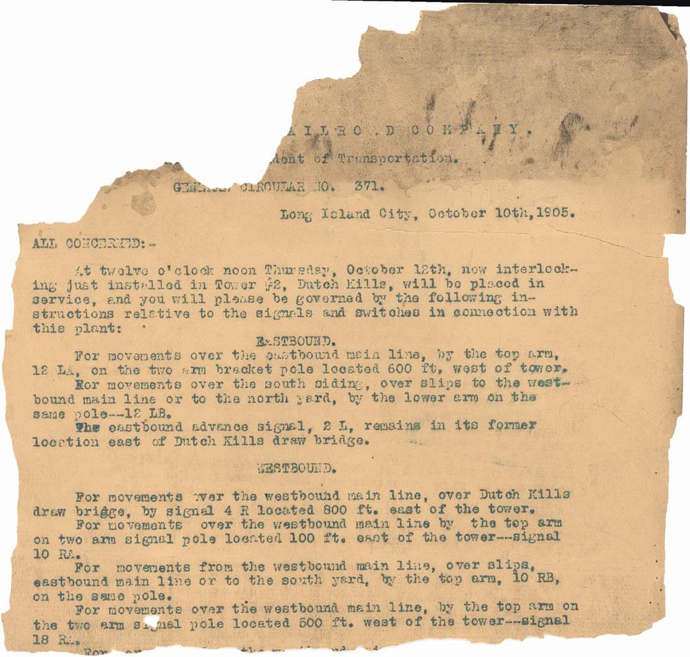
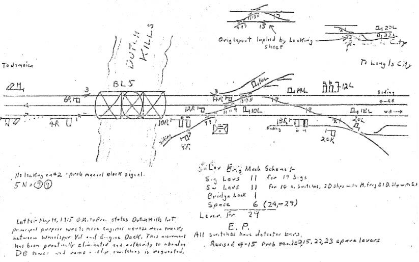
In October 1905 a straight electric or electo-pneumatic machine replaced the Saxby & Farmer mechanical machine in Tower Number Two. |
|
A June 5, 1908 article in Railroad Age Gazette calls this a 29 lever Union Electric machine. "...... A very busy plant, the lever movements in the summer averaging 2600 in 24 hours." Henry Wilhelm thought it had been an electro-pneumatic plant. |
THESE TWO PHOTOGRAPHS ACCOMPANIED THE ARTICLE.
|
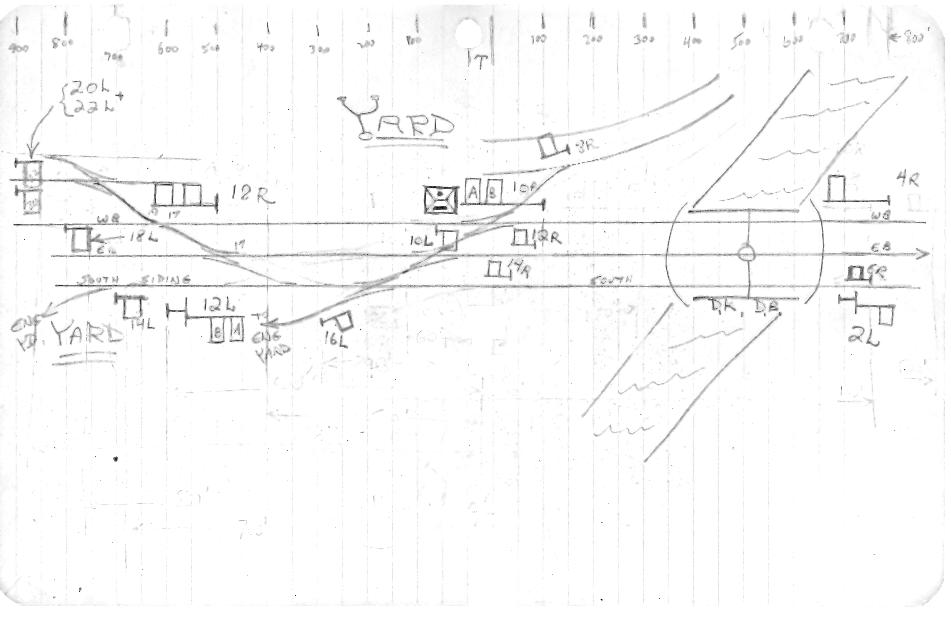
This plan shows sigs 20L and 22L protecting a double slip switch, north of main tracks west of tower. |
|
Henry Wilhelm shows only 20L and single switches instead of a double slip. He notes: "revised 4-15 Probably made 2, 15, 22, 23 spare levers." |
|
Letter May 14, 1915 G.M. to Pres. states Dutch Kills Int. "principal purpose was to move engines across main tracks between Wheelspur Yard and Engine Dock. This movement has been practically eliminated and authority to abandon DB Tower and remove slip switches is requested." |